Diagnosing hardware failures in PV systems using I-V curve tracers
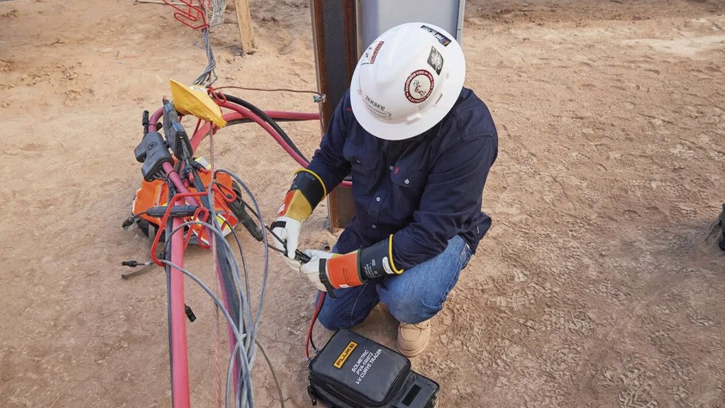


Photovoltaic (PV) systems are subject to various hardware issues that can significantly impact their performance. Diagnosing these issues accurately is crucial for maintaining system efficiency and longevity. I-V curve tracingis a powerful tool that helps technicians identify specific hardware failures in PV systems. This article provides a detailed guide on troubleshooting common hardware issues using I-V curve tracers.
Common Hardware Issues in PV Systems
PV systems can experience several module-related problems that affect their performance. Here are some of the most common issues:
- Shorted Bypass Diodes
- Microcracks in PV Cells
- Connector Failures
- Potential Induced Degradation (PID)
- Hotspots
- Shorted Bypass Diodes
Description: Bypass diodes are integrated into PV modules to protect cells from overheating and damage due to partial shading or issues within the module. A shorted bypass diode can cause significant performance issues, leading to a reduced voltage output.
Symptoms:
- Low Open-Circuit Voltage (Voc): The I-V curve will show a significantly lower Voc.
- Stepped I-V Curve: The curve may display steps or abrupt changes in slope.
Troubleshooting Steps:
- I-V curve tracing: Use the I-V curve tracer to identify deviations in the Voc and detect steps in the I-V curve.
- Visual Inspection: Inspect the module for visible signs of damage or overheating.
- Multimeter Test: Test the bypass diodes with a multimeter. A shorted diode will show continuity in both directions.
- Replacement: Replace the affected module or bypass diode as necessary.
Case Study: In a commercial PV installation, technicians noticed a drop in system performance. I-V curve tracing revealed a low Voc in one string. Testing the bypass diodes confirmed a shorted diode. Replacing the affected module restored the system's performance.
7. Microcracks in PV Cells
Description: Microcracks are small cracks in PV cells that can occur during manufacturing, transportation, and installation and due to weather events like high wind or hail. These cracks can grow over time, leading to reduced performance and potential failure.
Symptoms:
- Stepped or Irregular I-V Curve: The I-V curve may show steps or irregularities, indicating current mismatch.
- Reduced Current Output (Isc): The overall current output may be lower than expected.
Troubleshooting Steps:
- I-V Curve Tracing: Identify deviations and steps in the I-V curve.
- Electroluminescence Testing (EL): EL testing applies a reverse-bias current to a string of modules and uses a specialised camera to detect microcracks. This is the most accurate way to detect microcracks, but EL equipment is currently expensive, and the test is labour-intensive.
- Infrared (IR) Imaging: Use an IR camera to detect hot spots, which may be indicative of microcracks.
- Replacement: Replace modules with significant microcracks.
Case Study: A utility-scale PV farm experienced a gradual decline in performance. I-V curve tracing and IR imaging identified microcracks in several modules. Replacing these modules improved the system's overall output.
8. Connector Failures
Description: Connectors are critical components in PV systems. Failures can result from corrosion, poor installation, or physical damage, leading to increased resistance and reduced performance.
Symptoms:
- Low Voltage Ratio: The I-V curve will show a lower-than-expected voltage ratio (Vmp/Voc).
- Irregular I-V Curve: The curve may display irregularities or a lower-than-expected current output.
Troubleshooting Steps:
- I-V Curve Tracing: Identify irregularities in the I-V curve.
- Visual Inspection: Inspect connections for signs of corrosion, damage, or poor installation.
- Electrical Testing: Use a multimeter to test for continuity and resistance in connectors.
- Thermal Imaging: Use a thermal camera to detect connectors that are operating at a higher temperature when compared to other connectors under the same environmental conditions.
- Replacement or Repair: Repair or replace faulty connectors.
Case Study: A solar carport installation had inconsistent performance. I-V curve tracing showed irregular I-V curves. Inspection revealed corroded connectors. Replacing the connectors restored consistent performance.
9. Potential Induced Degradation (PID)
Description: PID is a phenomenon that occurs when voltage differences between the PV system and the ground lead to leakage currents, causing module degradation.
Symptoms:
- Low Voc and Isc: The I-V curve will show both low Voc and Isc.
- Degraded I-V Curve: The curve may appear flattened and degraded over time.
Troubleshooting Steps:
- I-V Curve Tracing: Identify degraded I-V curves with low Voc and Isc.
- IR Imaging: Use an IR camera to detect areas of degradation.
- Electrical Testing: Test for leakage currents and potential differences.
- Mitigation: Install PID mitigation equipment or replace affected modules.
Troubleshooting Guide for Common Hardware Issues
| Issue Type | Symptoms | Troubleshooting Steps |
| Shorted Bypass Diodes | Low Voc, stepped I-V curve | I-V curve tracing, multimeter test, replace diodes |
| Microcracks in PV Cells | Stepped/irregular I-V curve, reduced Isc | I-V curve tracing, visual inspection, electroluminescence testing, IR imaging |
| Connector Failures | Low voltage ratio, irregular I-V curve | I-V curve tracing, visual inspection, electrical testing |
| Potential Induced Degradation (PID) | Low Voc and Isc, degraded I-V curve | I-V curve tracing, IR imaging, PID mitigation |
| Hotspots | Stepped/irregular I-V curve, visible hotspots | I-V curve tracing, IR imaging, cleaning/repair |
Case Study: A PV farm in a high-humidity area experienced significant PID. I-V curve tracing and IR imaging confirmed the issue. Installing PID mitigation equipment and replacing severely affected modules restored performance.
10. Hotspots
Description: Hotspots occur when a part of a PV module becomes significantly hotter than its surroundings, often due to shading, soiling, or cell damage, leading to reduced performance and possible damage.
Symptoms:
- Stepped or Irregular I-V Curve: The I-V curve may show steps or irregularities.
- Visible Hotspots: Detected using IR imaging.
Troubleshooting Steps:
- I-V Curve Tracing: Identify steps or irregularities in the I-V curve.
- IR Imaging: Use an IR camera to detect hotspots on the modules.
- Visual Inspection: Inspect for shading, soiling, or physical damage.
- Cleaning and Repair: Clean soiled modules and repair or replace damaged modules.
Case Study: A residential PV system had reduced output. I-V curve tracing and IR imaging identified hotspots caused by bird droppings and a cracked cell. Cleaning the array and replacing the affected module resolved the issue.
Conclusion
I-V curve tracing is an invaluable tool for diagnosing module failures in PV systems. By identifying specific issues such as shorted bypass diodes, microcracks, connector failures, PID, and hotspots, technicians can take targeted actions to restore and optimise system performance. Regular use of I-V curve tracers, combined with thorough inspections and appropriate repairs, ensures that PV systems operate efficiently and reliably.
Frequently Asked Questions (FAQs) About Diagnosing Hardware Failures in PV Systems Using I-V Curve Tracers
Q1: What are the common hardware issues in PV arrays?
Common hardware issues include shorted bypass diodes, microcracks in PV cells, connector failures, potential induced degradation (PID), and hotspots.
Q2: How can I detect shorted bypass diodes?
Use I-V curve tracing to identify low Voc and steps in the I-V curve. Confirm with a multimeter test for continuity in the bypass diodes.
Q3: What tools can help identify microcracks in PV cells?
I-V curve tracers, visual inspections, electroluminescence testing, and infrared (IR) imaging can help detect microcracks.
Q4: How do connector failures affect PV systems?
These failures increase resistance and reduce performance, often visible as irregularities in the I-V curve, low voltage ratios, and high-temperature connections in thermal images.
Q5: What is Potential Induced Degradation (PID), and how can it be mitigated?
PID is caused by voltage differences, leading to leakage currents and module degradation. Mitigation includes installing PID mitigation equipment and replacing affected modules.
Article Enquiry
Email Article
Save Article
Feedback
To advertise email advertising@creamermedia.co.za or click here
Research Reports

Projects
Latest Multimedia

Showroom
M and J Mining are leading suppliers of physical support systems as used by the underground mining industry. Our selection of products are not...
VISIT SHOWROOM
Smart energy storage solutions for efficient, safe, and profitable power.
VISIT SHOWROOM

Press Office
Announcements
What's On
Subscribe to improve your user experience...
Option 1 (equivalent of R125 a month):
Receive a weekly copy of Creamer Media's Engineering News & Mining Weekly magazine
(print copy for those in South Africa and e-magazine for those outside of South Africa)
Receive daily email newsletters
Access to full search results
Access archive of magazine back copies
Access to Projects in Progress
Access to ONE Research Report of your choice in PDF format
Option 2 (equivalent of R375 a month):
All benefits from Option 1
PLUS
Access to Creamer Media's Research Channel Africa for ALL Research Reports, in PDF format, on various industrial and mining sectors
including Electricity; Water; Energy Transition; Hydrogen; Roads, Rail and Ports; Coal; Gold; Platinum; Battery Metals; etc.
Already a subscriber?
Forgotten your password?
Receive weekly copy of Creamer Media's Engineering News & Mining Weekly magazine (print copy for those in South Africa and e-magazine for those outside of South Africa)
➕
Recieve daily email newsletters
➕
Access to full search results
➕
Access archive of magazine back copies
➕
Access to Projects in Progress
➕
Access to ONE Research Report of your choice in PDF format
RESEARCH CHANNEL AFRICA
R4500 (equivalent of R375 a month)
SUBSCRIBEAll benefits from Option 1
➕
Access to Creamer Media's Research Channel Africa for ALL Research Reports on various industrial and mining sectors, in PDF format, including on:
Electricity
➕
Water
➕
Energy Transition
➕
Hydrogen
➕
Roads, Rail and Ports
➕
Coal
➕
Gold
➕
Platinum
➕
Battery Metals
➕
etc.
Receive all benefits from Option 1 or Option 2 delivered to numerous people at your company
➕
Multiple User names and Passwords for simultaneous log-ins
➕
Intranet integration access to all in your organisation